
|
The 8th and 9th of March it was time for the big electronics fair in our home town. Röcklinger was there to take part of the event. Many interesting things to see and new contacts were established. As you may know, we have new products and new designs under development and we are looking for reliable partners to work with. It seems like Hans enjoyed the fair and was very happy with the outcome, you decide.  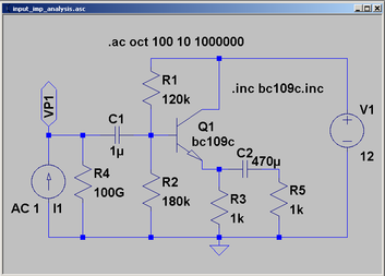 This is how we at Röcklinger set up LTspice for input impedance analysis Use a current source with the fixed magnitude of 1 Ampere:
From Ohms law we find that U = I * Z and as the current source is set to 1 Ampere then in this case the magnitude of the Voltage is equal to the Impedance. Do an AC analysis and plot voltage of interest divided by the current source. Set the scale of Y-axis to linear and voila impedance is ploted. 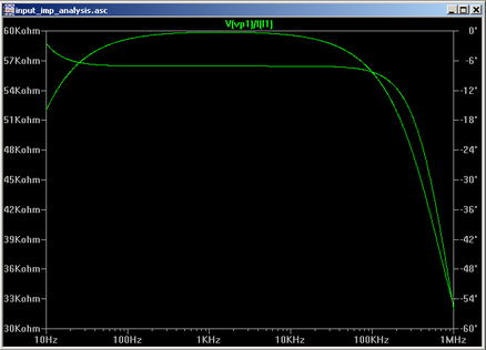  Here is another tip for you to tackle a possible problem with burst of the DC supply. As usual we at Röcklinger are happy to share our knowledge for those interested in detail construction. In order to take care of the burst in the input we recommend the following circuit design: 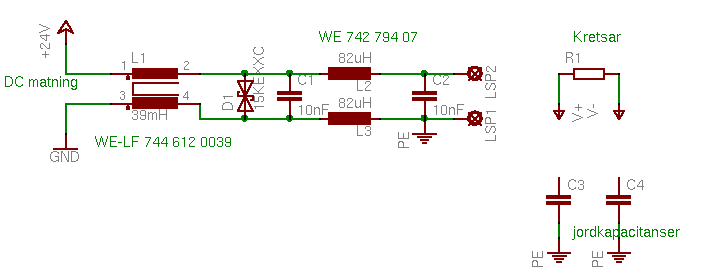 The circuit above keeps + and - together at the feed to the logic. If you still have problems with interference it is usually due to that the voltage across the component supply inputs are different due to different ground capacitance at different locations on the PCB. Usually, the fault lies in the ground plane in these cases.
We at Röcklinger are very happy to share construction and design tips for you out there who are exploring the wonderful world of sound perfection and creating your own circuits. In order to protect against surge in DC inputs, bidirectional diodes such as the SM15T39CA from Microelectronics for instance, are very often used. The location of these diodes define the characteristics that the input circuit will have. If you place the diode fore the common-mode choke coil the diode and fuse will break when you put a disturbance in the DC input. Instead, place the diode after common-mode choke and you get a resistor in series with the diode thus limiting the inrush current. 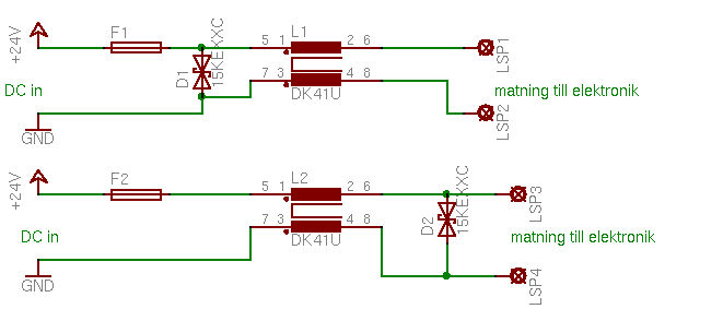 The first amplifier Röcklinger launched was a headphone amplifer, build with tubes and with OTL technique. OTL stands for Output Transformer Less. To learn more what OTL is we share with you some usefull links for the curious.
We at Röcklinger always simulate the electrical design first, then we build the circuit, measure and improve the design. This loop continues until we are confident that the final design is flawless. We also like to share and prove our design. So here is a tip on how to simulate input impedance using LTspice. Use a current source with the fixed magnitude of 1 Ampere:
From Ohms law we find that U = I * Z and as the current source is set to 1 Ampere then in this case the magnitude of the Voltage is equal to the Impedance. Do an AC analysis and plot voltage of interest divided by the current source. Set the scale of Y-axis to linear and voila impedance is ploted.  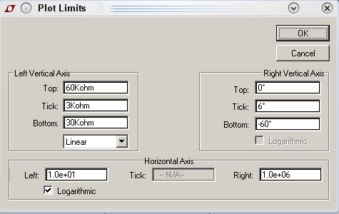 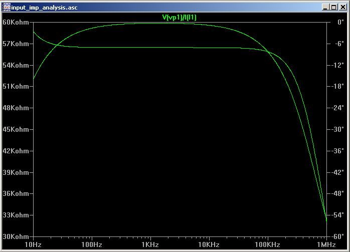 |
AboutFollow our journey on perfecting the art of high fidelity sound. Archives
March 2017
Categories |
 RSS Feed