Röcklinger HiFi
  • Home
  • Products
    • LEXIA
    • AURIA
    • - Upcoming
    • - Legacy >
      • PHA2
      • PHA1
      • HPA1 OTL
  • Articles
  • About
  • Buy now

Articles

Straight from the engineers of Röcklinger

To measure input impedance

22/10/2016

 
We at Röcklinger always simulate the electrical design first, then we build the circuit, measure and improve the design. This loop continues until we are confident that the final design is flawless. We also like to share and prove our design. So here is a tip on how to simulate input impedance using LTspice.

Use a current source with the fixed magnitude of 1 Ampere:
  1. In parallel with the input.
  2. In a point in the circuit where analysis is required.
A shut resistor is not needed if Rinput is in parallel with with the current source. In other cases use a 100G resistor in parallel with the current source.
From Ohms law we find that U = I * Z and as the current source is set to 1 Ampere then in this case the magnitude of the Voltage is equal to the Impedance.
Do an AC analysis and plot voltage of interest divided by the current source. Set the scale of Y-axis to linear and voila impedance is ploted.
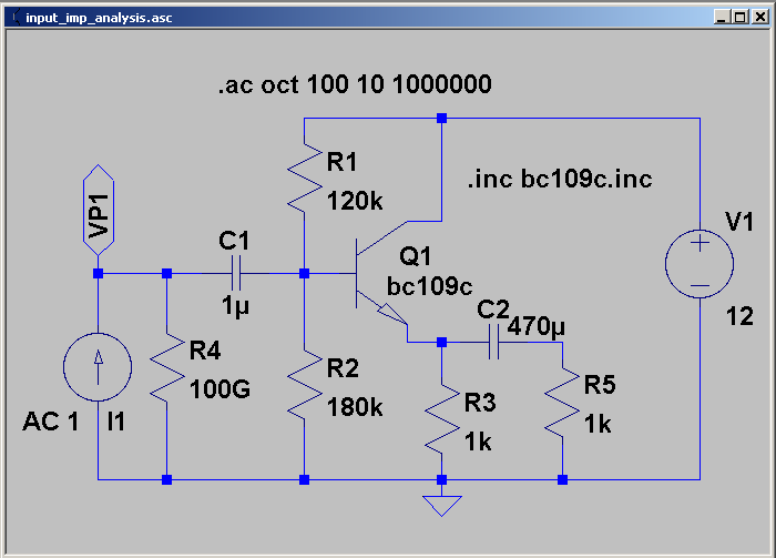
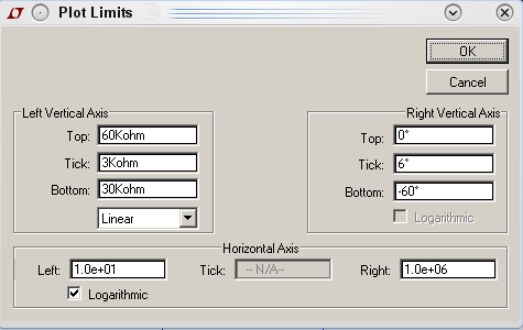
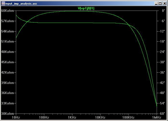
Picture
Picture
Picture

    About

    Follow our journey on perfecting the art of high fidelity sound. 

    Archives

    March 2017
    February 2017
    January 2017
    December 2016
    November 2016
    October 2016

    Categories

    All
    Electrical
    General
    Simulation

    RSS Feed

  • Home
  • Products
    • LEXIA
    • AURIA
    • - Upcoming
    • - Legacy >
      • PHA2
      • PHA1
      • HPA1 OTL
  • Articles
  • About
  • Buy now